

cable wire splicing and termination
Rubber covered, Taped, Braided, Compounded wires.
(i) Single braid 250 V: Such type of wire is also called simply as V.L.R. wire. These are used generally for ordinary electrical wiring in casing, capping or conduit wiring.

Rubber covered, Taped, Braided, Compounded Wires.
The general construction of the wire is It consists of a tinned (to prevent the rubber sticking to the conductor) copper or aluminium conductor covered with a layer of rubber insula- tion. over this rubber insulation is put upa cotton protective braid which is usually saturated with flame retarding and moisture-resistant com- pound. Finally it is finished with a wax for cleanliness and for helping the pulling action of it into the conduits. Such type of wire is also called as S.B.R.C. wire (single-braid rubber-covered). The thickness of the rubber insulation depends upon the voltage for which the wire is required, i.e., whether it is for 250 V or 600 V. The wires required for higher values of current are usually stranded, in case, copper issued as conductor. Stranded wires with aluminium conductor are not manufactured. These wires are provided with two protective cotton braids and are usually called as D. B.R.C. Std. (double-braid rubber-covered stranded) wires.

Double Braid
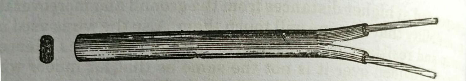
(ii) Lead Alloy Sheathed Wires. Such types are recommended where the climatic condition is not dry, but has a little bit of the moisture. Ordinary S.B.R.C. wires are specified for reasonably dry locations, so in order to use rubber insulated wires in damp conditions, the ordinary wires are covered with a continuous sheath of lead. The lead covering is usually thin, about 1.25 mm. thick. The lead alloy sheathed cables are usually available in the following types:
(1) Single core lead-sheathed.
(2) Flat twin lead alloy sheathed (as shown in Fig. 3.6)
(3) Flat lead alloy sheathed 3-core.
(4) Flat twin lead alloy sheathed with E.C.C. (earth continuity conductor).

Lead Alloy Sheathed Wires
These types of lead sheathed wires provide only a little mechanical protection. The more stronger and mechanically protected cables are used for laying under the ground.
(iii) Tough Rubber Sheathed (T.R.S.) or Cab Tyre Sheathed (C.T.S.) Wires.
The lead sheathed cables are costlier and are quite heavy in weight. The T.R.S. cables have properties similar to that of lead sheathed cable, but is much cheaper. The ordinary wire is provided with rubber insulation which is not water resistant; but the T.R.S. wires are provided with a tough rubber compound which does not deteriorate even after long exposure to moisture's. So it can well be used in wet locations. Such wires are also available in single core, twin core, 3-core and twin and an earth continuity conductor. (a) shows a single core cable while (b) shows a twin core cable.
(iv) Weather-Proof Wire.
The weather-proof wires are for outdoor purposes, i.e., they are run between buildings. Such wires when used

Tough Rubber Sheathed (T.R.S.) or Cab Tyre Sheathed (C.T.S.) wires
are suspended at higher distances from the ground and moreover there is no possibility that any one will touch them. Also the wires used must be cheap and resistant to atmospheric varying conditions. Hence the insulation provided over it is not the same as that for indoor wiring. Although the T.R.S. wires can be used, yet the T.R.S. wires are not much cheaper. Such type of wires consists of 3 braids of fibrous yarn provided over the copper conductors. The copper conductors are not usually tinned. Before these braids are applied they are thoroughly saturated with a water-proof compound.

Weather-proof Wires
(v) Flexible Wires.
The wires used for household appliances such as heaters, irons, refrigerators, lamps etc., must be durable and very flexible. The flexibility is required firstly from the point of view of handling the equipment, secondly to prevent the wires from break. These flexible wires are also called as lamp cords. The flexible cord usually consists of two separately insulated flexible stranded condue- tors. The flexible wires are called as 14/0.0076 or 162/0.0076 which means that there are 14 or 162 strands of copper wire each having a diameter 0.0076 inch or 0.1930 mm. which is equivalent to 36 S.W.G. wire. There are different types of flexible wires. They are:
(a) Twin Silk Cord.
It consists of two cores but each of these consists of a number of fine copper conductors stranded together. Over each conductor is given a layer of cotton, which prevents the sticking of rubber to the copper conductor. After cotton layer covering the layer of rubber insulation is followed up by a loose braid of cotton and finally the conductors are laid side by side and silk insulation is provided over them.

Twin Core Flexible Wire
(b) Twin Rubber insulated cord.
It is also similar to that of te silk cord wire and consists of two stranded conductors each covered wi cotton in order to prevent rubber sticking to the conductor. Then two conductors are embedded in a solid mass of rubber insulation whid is build up to a full size of finished wire and there is no further provinio of any other insulation. The two conductors in the rubber insulation a so laid as to form a depression in the middle of them which facilitates in separating the two conductors at the termination of the wire in receptacles ete. The rubber provided for such insulation must be of much higher grade than is used for ordinary wire insulation.
Twin Rubber insulated cord
(c) Twin Twisted Cotton Braided Flexible Wire.
In this case each of the conductor is insulated as in the silk flexible cord, i.e., each conductor is cotton covered, followed up with a layer of rubber insulation and after this comes a braid of cotton, thus, completing the insulation of the single conductor. Then two such conductors are twisted together. Usually the two insulated conductors twisted together have rubber insulation of two colours i.e., red and black.

Twin Twisted Cotton Braided Flexible Wire
(d) Twin T.R.S. Flexible Wire.
The flexible lamp cords mentioned earlier are not much resistant to moisture and also they cannot withstand much wear and tear. The T.R.S. flexible wire consists of two or more insulated conductors twisted together as in case of twin twisted flexible wire. The open space in between the twisted conductors is filled up with cotton or jute threads, so as to form a round assembly. Over this assembly is provided a loose cotton braid and then a final layer of high grade of tough rubber.
In case of a wire better resistant to moisture, rubber filler is used to make the twin twisted conductors assembly round and the wire is finished off with an outer jacket of cotton which is impregnated with a moisture-resistant compound. Such a wire is called as reinforced wire.

Twin T.R.S. Flexible Wire
WIRE SPLICING AND TERMINATION In all jobs of wiring, splicing (jointing) and termination is a neces- sity. The jointing is required since the wires are manufactured in 100-metre lengths and the total length of wire used for house wiring may be more than 100 metres. The termination of wires is needed, as the wires are to be connected to switches, holders, receptables etc. It in important to note that all joints made must be mechanically and electri- "punos kroa The jointing conductors and wires should always be carried out at outlets, i.e., in switches, ceiling roses using the looping in system or in junetion boxes used specially for this purpose. Splicing should never be done in conduit runs. But sometimes when repairing old works, jointing becomes a necessity.
WESTERN UNION SPLICE OR TWIST SPLICE
The western union splice can be completed in four steps which are:
(a) Removing insulation.
(b) Mechanically jointing the conductors.
(e) Soldering the joint.
(d) Tapping the soldered joint.
(a) Removing insulation. For joining two conductors together, first their insulation is removed. The insulation of the wire should not be cut by holding the knife at right angles to the conductor which cuts the insulation (a); but it should be removed by holding the knife at an angle just as in the case of sharpening a pencil, as represented(b) taking care not to injure the copper condue-(a) Insulation removed in a wrong way tor.

Correct method of removing the insulation
The removing of insulation in a tapered fashion is a necessity since it facilitates better jointing and insulating thejoint. After the insulation is removed in a tapered fashion from a certain portion ofa wire, the insulation form the remaining portion of wire can be removed with one pull of pliers up to the end of the wire. For joining insulated conductors it is necessary to remove braid only for a required length ie., 2.5 cm. approximately.

Pulling insulation with a Pliers
(a) Then the bare conductors of the two wires to be joined together are gently cleaned with sand paper.

(b) Mechanically jointing the conductors. For making the joint, cross the two bare wires at ends at a distance of about 2 cm. from insulation of either of the wire, the wires are crossed or neck turned (b). The crossing or neck turn of the conductors prevents the

(c) Showing one of the conductor bent around the other
Two wires being separated out under a pressure. Now with the help of the forefinger and thumb or with pliers, make five to eight turns, as shown. The remaining excess of the conductor should be cut away with the pliers and the turns should be tightened with it. Now a similar process is repeated with the other conductor and is finished off in a similar manner.

Finished join
(c) Soldering the Joint.
The mechanically bound joint made earlier cannot be said to be mechanically secure. In order to make the mechanical joint as strong as continuous length of the wire, it is necessary to solder the joint. The soldering can be done either with the help of a soldering iron or by means of a blow lamp. Before soldering it is essential to clean the surface and to make it free from dirt, grease etc. Now apply soldering paste around the joint both at the top and bottom of it. The application of soldering paste is not necessary if resin-core solder is used which acts as a flux. Now heat the joint with the help of a blow lamp heating it with the tip of the flame. It is essential to heat the joint up to a proper temperature; if it is not properly heated, proper soldering cannot be done, and if the joint is over-heated the conductor is weakened and becomes brittle. The proper temperature is tested with a piece of solder wire, which when placed over the joint should melt. At that instant, apply solder over whole of the joint as shown in Fig. 3.16. The solder should be applied several times until the solder floats or runs completely through the splice.

Soldering the joint
(d) Taping the splice.
The soldered joint must now be provided with an insulation, the thickness of which must be equal to that of the wire. For the wires generally used for house-wiring purpose rubber tape, friction tapes and black tape should be used. The method of applying the rubber tape The tape should half overlap the previous turn, and the type should be stretched a bit until whole of the joint is covered and a bit of the insulation of the other wire is also covered. Now apply friction tape in a similar fashion to that of rubber tape.

Method of applying tape
MARRIED JOINT For a wire having one strand only, the joint made is called twisted joint, but for wires having a number of strands, the joint made is called as married joint. The following points show how the joint is made:
(1) Remove the insulation about 10 em. on each wire with the help of knife in a tapered fashion as explained in Twist Splice.
(2) Remove braid for about 2.5 cm. on each wire.
(3) Separate the strands of each wire by twisting the stranded conductors in opposite direction to that of winding.
(4) Clean each of the strand gently with sand paper.
(5) Retwist the strands for a length of about 0.5 cm.
(6) Bind the twisted wire with a bind- ing wire.
(7) Cut off the middle strand with the help of a pliers.
(8) Spread the individual strand
(9) Bring the two wires end top end with all the strands intersecting.

Intersecting of strands of two wires
(10) Hold one of the wires in the left hand and wrap one of the strands of the other wire around the twisted conductor in opposite direction (c). Repeat the process with the other strand an so on.

Twisting of strands
(11) Round off the ends with mallet or pliers.

Finished joint
(12) Repeat the process with the other side of the wire. The joint is then soldered and insulated as explained in article 3.27.
SINGLE BRANCH SPLICE OR A TAPE JOINT Sometimes it is necessary to tap the electrical energy from a running line. In that case, only one free end of the wire is available and thus the twist joint or western union joint is not possible which neces- sarily requires two free ends. So in such circumstances a T joint is necessarily made. The following steps explain the process of joining.
(a) Remove the insulation of the running wire (a) for a length of about 2.5 cm. with care and precautions as explained earlier.
(b) Remove the insulation of the branch wire for a length of about 7.5 cm.

(b) Removing insulation of a branch wire
(c) Gently clean the conductors with the help of a double zero sand paper.
(d) Now keeping the branch wire at 90° to the running wire and with insulation of both wires near to each other make a neck turn as shown in Fig. 3.19 (c) which guards against the slipping of the joint under pressure.

Neck tum for makingT Joint
(e) With the branch wire now give 5 to 8 turns as in the case of western union splice.
(f) Cut off the excees of the conductor.
(g) Now round off the conductor end with the help of a pliers or mallet. The finished joint.

Finished T Joint
The splice is then soldered and insultated with a tape as already explained in article 3.27.
DOUBLE BRANCH SPLICE
The double branch splice is used when the electrical energy is required to be sent in two directions at right angles to each other. Such a splice is nothing more than that of two single branch splices in opposite direction, so the method of obtaining such a joint is the same as that of a single branch splice. Figure 3.20 represents the double branch splice.

Double branch splice
TAP JOINT FOR STRANDED WIRES For stranded wires the single branch splice or the tap joint is made as explained in steps indicated.
(a) Remove insulation of the running wire for a length of about 5 cm.
(b) Similarly remove insulation of the tapping wire for a length of about 7.5 sm.
(c) Clean the conductors gently with sand paper.
(d) Separate the strands of the running wire into two groups.
(e) Insert the tap wire into the opening made in the running wire.
(f ) Divide the strands of the tap wire into two groups.

Finished Tap-joint
(g) Wrap one of the strands around the running wire, then wrap the second strand and so on.
(h) Wrap one of the strands around the running wire in the opposite direction to the previous one
(i) Round off the ends of the conductor with a pliers or mallet.
(j) Solder the join as explained earlier and provide tape.
FLEXIBLE CORD SPLICING
Sometimes it is necessary to provide a joint in a twin core cord. In such cases the two joints of the cores must be staggered as represented.Such a splice has double advantages. Firstly it avoids the

Joint in flexible twin core cord
accidental short circuit between the two cores, secondly it does not make the splice bulky.
PIGTAIL JOINT
The pig tail joint is the most important joint, since it is often required of termination of the wires in switches, holders etc. Moreover it can easily be made and un-made. For making such a joint:
(a) Remove insulation from the two wires as shown earlier for a length of about 5 cm.
(b) Gently clean both the conductors.
(c) Keep the two wires with their insulation parallel.
(d) With a pliers make a number of twists.
(e) Keep the length of the twists about 2.5 cm. and cut off the excess wire.
(f) Round off the corners with a mallet.

PIGTAIL JOINT
PIGTAIL JOINT OF A SOLID CONDUCTOR AND A FLEXIBLE WIRE Such a joint is made in a manner similar to that of an ordinary pigtail joint, except that after wrapping the stranded wire, round the solid conductor for a length of about 2.5 cm., the solid conductor is bend back parallel to the wire as shown in Fig. 3.24. and then the joint is soldered and provided with a tape.(a). For providing tape, care should be taken to know that no end of the joint is left without a tape, so for this purpose, the tape is started between the wires as in Fig. 3.25 (a). The wires are brought together tightly and provided a layer of tapes as in Fig. 3.25 (b). Then wrap the tape half overlap. At bottom, the tape is provided without stretch as shown in Fig. 3.25 (e). Complete the tape as in Fig. 3.25 (d). Over this rubber tape is provided and then a friction tape.

Finished pigtail joint of a solid conductor and a Flexible Wire
TERMINATION OF WIRES AT TERMINAL SCREWS
When it is required to terminate an 18 S.W.G. wire or lighter wire to a screw, the insulation from the wire is removed with the care to remove it in a tapered fashion. The conductor is bent in the form of a loop. It should be remembered that the loop of the wire must be made in the same direction in which the terminal screw is to be turned for lighting; such an action closes the loop in the process.(a) represents the correct termination. While making a ter- mination, the insulation of the wire is brought near to the screw; it is a wrong method to keep it away

(b) at such a termination causes shot circuit. Also the excess wire. (c) be cut off and the wire end is tucked inward to avoid exposing bare portion of the conductor

(a) Bending of conductor in the form of loop (b) Wrong method of forming the loop. (c) Excess wire needs cutting.
For heavier wire either a solderless connection is made. (a) or a soldering lug. (b) is used for connection. The heavier conductors are soldered to this lug which is terminated with a bolt.

Solderless connection for heavier wire / Soldering lug


No comments
If You Have Any Doubts, Please Let Me Know